Fanleaf's Huge 42 COB Array Build Plus Other Builds

Hey Fan, I’m back…

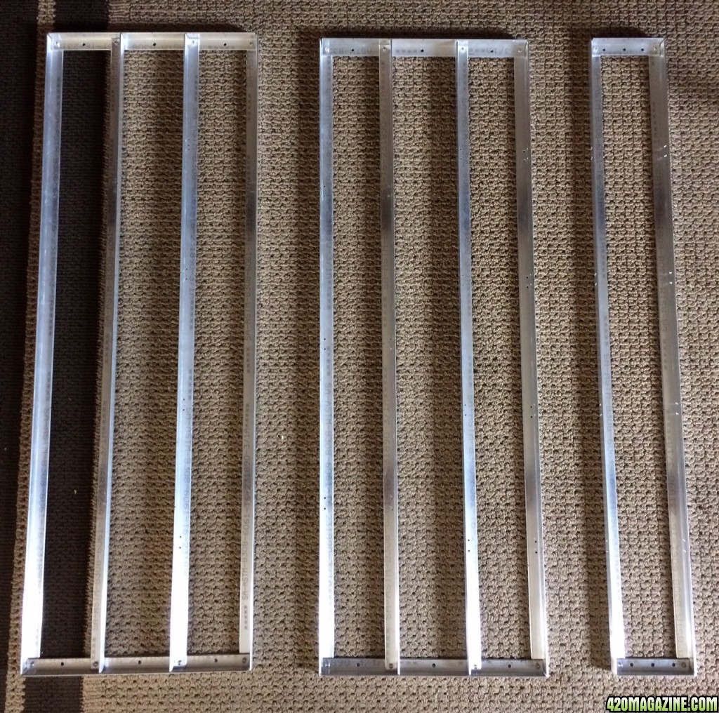
I was finally able to work on my build. I used autocad to help me place heatsinks and measure out distances. (img 1).

img_1.png


My first rail was trashed. I drilled too many holes in it and f ucked it up. The nuts and bolts I used to hold it together didn’t work out. It was too loose & too much work. I used rivets instead!! Best decision ever!! Quick n easy & tight!! I also didn’t like the 3000k & 5000k cobs were only 2” apart. So I changed it to 5” and that placed my cobs about 12” apart off center.

Here is the breakdown of the rails in img 1: The rail on the left includes (4) 3000k & 3 (5000k). I built 4 of these. The rail on the right is (4) 3000k and only built 1.

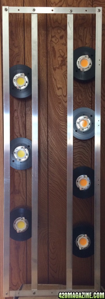
I initially was only going to build one 4x4 rail with 2 left rails + 1 right rail (18 cobs total) (see img 2).

img_25.jpg


But if I wanted to expand my build to cover a 4x8 area I would end up with (8) 3000k cobs in the center of the 4x8 & figured it would create a large hot spot of reds. So I decided to have 2 left rails + 1 right rail in the center followed by 2 more left rails to even out the space (32 cobs total). No pic for this sorry.

Heres a pic of a left rail with heatsinks & cobs (img 3).

img_31.jpg


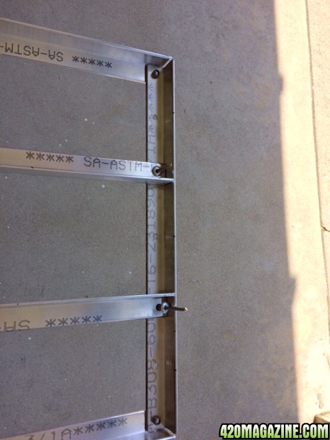
All the heatsinks, cobs, and wiring is in place, but now I have a problem. Since I decided not to build a 4x4 rail and went with a 48”x16” rail I’m having issues trying to figure out how to connect my cobs on different rails to the same driver (img 4).

img_42.JPG


The (4) 3000k on the left need to be connected to (2) 3000k on a separate rail (the ones Im pointing at). I'm wiring in series and when I hang them they will be 5” apart. I want to be able to disconnect them easily and not worry about pulling out the wires. I was thinking of using wagos but I’m not sure if I can pull out the wires once they are in place. Any idea’s how I can connect them? (This would also be used to connect the (3) 5000k on the left side to the (3) 5000k on the right side)

So far, the framing has taken the longest. I’m having a hard time visualizing how to connect the drivers to the cobs and connecting them to a central station (electrical box) with the inline displays I’ve seen Fan & buck do. Can you guys give me more instructions on this part.

Ok, its late. I’m outta here. Thanks everyone!!
 
Hey Fan,

I know you asked for a step by step, so here it is. It was late last night and didn’t have time to write it up. I have some pics, but I’ll try to upload em later. I’m still not finished so I’ll come back and update this. If this is too much, let me know and I’ll take it down or you can delete if you like.

Here is an overall step by step view of my build…

#1 Cut (10) 48” pieces of 1/8” Aluminum angle 6061 (aka. AA) [Outer frame beams - length]
#2 Cut (8) 47 ¾” pieces of AA [beams go inside outer frame to help hold cobs - length]
#3 Cut (8) 16” pieces of AA [smaller outer frame beams – width]
#4 Cut (2) 5 ¾” piece of AA [smaller outer frame beams – width]

Drilled my rivet holes (used 1/4" aluminum rivet) on all length pieces (#1, #2) [ used 17/64” drill bit] - Measured ½” from the top edge of AA & also measured ½” from the wall of the AA. To simplify the process, I only measured 1 hole & ended up marking my drill press table accordingly, so I knew where to place the rest of my length beams.

Drilling the rivet holes for the width pieces (#3, #4 above) [17/64” drill bit]– I tried the same technique as above but the holes would never line up. Tried this several times, with a hand drill & drill press. Since the width piece goes on top of the length piece the alignment was off. To correct this I aligned the 2 AA pieces to form an “ L “ & clamped it. The hole I previously drilled in the length beam #1 was the guild for the hand drill on the width beam (This is how Fan drilled his holes). Then I marked my drill press table so I knew how to drill the rest of my width beams. After my 2nd completed rail, I went back to the remaining #3 pieces & drilled rivet holes for the #2 pieces. I measured 5 1/16” from each end and drilled a rivet hole. Make sure you double check your frame. The thickness of the AA used and how its held together will changed your measurements.

Drilling the heatsink mounting holes (#1, #2) (used 9/64” drill bit ** let me double check this) - this was a B ITCH . On the heatsink the hole is approx 1/8 from the bottom of the heatsink but the AA 6061 has rounded corners so I was not able to accurately measure this distance upward from the inside corner of the beam. So I drilled several holes at slightly different heights. Then I put the heatsink on top of the AA beam & tried to insert the screw. I picked the height that was closest to being horizontally parallel and marked my drill press table. Now for the distance between mounting holes. I knew the distance from the start of 1 mounting hole to the end for the 2nd mounting hole was approx 15/16” and the distance in between the mounting holes was approx 5/8”. So I drilled 1 hole and tried to measure 5/8” away to drill my 2nd hole. This also took several attempts (sets of holes) to make it work. After every set I would put the heatsink on top & try to insert screws. Once I got his done I marked my drill press table. I actually figured out how to do this using the center point of my cobs. So if I knew my cobs were 10” apart, I would mark my beam every 10” and then use that 10” mark to drill my mounting holes. I just don’t recall how I did it. I’ll try to update this part later.

WARNING: Although this technique worked for mounting 1 side of the heatsink to 1 set of mounting holes on 1 beam, I could not get the mounting holes to align perfectly when I placed two beams together with the heatsink in between. I would insert 1 set of screws on one beam and had to turn the heatsink a few degrees left/right to insert the screws on the opposite beam. I tried everything. So if you figure this out please let me know.

Before riveting the rail, I would put it all together & just slip the rivets into the holes to make sure it all worked (do not fasten them). To double check my work, I would then add 80% of the cobs & screw them in. Once I was satisfied I would start riveting. I used Surebonder FPC86A-100 1/4-inch Aluminum Medium Rivets (amazon). If you are using 1/8” AA get the 9mm grip. I tried the ¼” grip and it was too long. The riveter (Astro 1423 13-Inch Heavy Duty Hand Riveter – amazon) would not brake the mandrel (top thinner part that goes into the rivet gun). I had to cut it off manually. Adding a washer worked but that was too much extra work. I just bought 9mm version & that fixed everything. I also clamped the pieces I was riveting to make sure the beams would not separate while riveting.

2nd WARNING: After performing the practice run above, I noticed that once I riveted the outer beams (#1 & #3) I had issues with the inner length beams (#2) alignment. Somehow the riveter made it tighter and the #2 length beams didn’t fit properly. I would cut off a small amt from 1 side to try to correct this. Sometimes I had to force the rivet in. Luckily, there was enough wiggle room to turn the heatsink and screw it in. You might want to save the #2 precutting until you get to this point.

This is the end of the framing.

FYI: Just so you know, before I cut all those pieces, I made sure I could build 1 rail completely with no problems. I probably trashed 2-5 rails with all my practice runs & drilling. I wouldn’t want you to prematurely cut and waste AA like I did, just because it didn’t’ workout as planned. Mine sure a ss hell didn’t. I had to make several adjustments on the fly because things didn’t turn out as expected.

For the cob placement on the heatsinks, I honestly just copied growmou5. His utube vids are legit.

In a nutshell, clean the heatsink with 91% rubbing alcohol, insert screws that the cob holder will use. Place the cob on the cob holder. Make sure you align the + sign on the cob to the + sign on the cob holder. I always placed the bottom corner of the cob underneath the + sign in 1st and then pushed down on the cob which pushed down on a lil spring lever that holds the cob in place. Then apply thermal paste to the the back of the cob (Fan uses Arctic Silver 5 & growmou5 uses Cooler Master IceFusion 200G). I got both. I’m totally new to this & since Arctic is more expensive & gives you a smaller quantity, I was hesitant to start with this knowing a lot of it would go to waste. But with cooler master you get a small bucket (exaggeration) and I was very comfortable applying generous amounts with a small plastic utensil and then using a small metal paint spatula (about the width of the cob) to lightly scrap off the excess & return it to the container. I’d then place the cob on the heatsink, press down and twist it a lil to even out it the thermal paste. I tighten the screws for the cob holder and then screw on light holder. I also marked the positive side with a ( + ) to help with wiring and placed it in the rails.

TIP: Do not tighten the heatsink mounting screws until after you finished wiring the cobs. That way you can tuck the wire between the cob and beams to help hold it in place. For the wire, I used 600V AC, 18 Gauge Black wire itm # 8428T4 from Mcmaster.

This project is not complete so I’ll come back and update this later later.

Hope this helps.
 
Hey Fan,

I know you asked for a step by step, so here it is. It was late last night and didn't have time to write it up. I have some pics, but I'll try to upload em later. I'm still not finished so I'll come back and update this. If this is too much, let me know and I'll take it down or you can delete if you like.

This project is not complete so I'll come back and update this later later.

Hope this helps.

Epic build man. You will love this light and never go back to anything else. Are you planning to add a few chips more to the outer edges or no? I ask because the edge par numbers are always low and why I always keep my outer chips no more than 6" off the walls but maybe yours does keep that in mind and I missed it. This is going to be a killer light bro and I'm really looking forward to more updates!

I'm going to re-read all of what you posted here shortly but wanted to jump in quick to say this is awesome!

Hey Fan,

Sorry I'm not replying sooner. I dont get notifications any more. :0/. I used to get emails.

The 3000k cobs are 6" from the end. I was debating between using 48" or 36"to build frame, but used 48" so I wouldn't have to take measurements & adjust the light when I hung it.


I couldnt edit previous post so I'll just add pics to clarify process.

Framing:

Just confirming Heatsink mounting holes were drilled with 9/64” drill bit.


(previus post) Before riveting the rail, I would put it all together & just slip the rivets into the holes to make sure it all worked.

The 2 center rivets is how I had the entire frame before riveting.

rail1.jpg


If if you look at the 2nd rivet from the right you see it doesn't fit properly. This is what my 2nd WARNING WAS referring to. The alignment changed once I riveted the outer frame.

This is how I quickly fixed it.

rail_2.JPG


While clamped I riveted it as well.


Heatsink & cobs:

Align the + sign on the cob to the + sign on the cob holder. From the back of the cob holder (on top right you'll see " + ") .
cob_2.JPG


Use the bottom of the cob to push down on the little lever and it snaps right in. Lever is on bottom, below the cob. (I struggled trying to use my figures).
cob11.JPG


Then apply thermal paste to the the back of the cob. (I cut plastic holder part from protein scooper)
cob_3.JPG


Lightly scrap off excess (used painters spatula).
cob4.JPG


Place on cob slightly press down & twist a bit to even out paste. Only tighten to the point where cob holder doesnt move. Not too tight. You might crack/break cob.
cob_5.JPG


Sorry if this was too much fan. When I started I didn't know s hit. I looked at you pics, asked a few q's, and then figure out how to get it done. I'm hoping this can help others with their DIY builds.

That's it for now. I still got to get the wiring completed.
 
I wish the hlg480's were out back in winter. I wouldn't had to buy so many drivers. I just ordered 2 , I'll swap em out when this cycle is over. I was wanting to use 80/20 sq profile aluminum for my frame. Do you have any ideas on mounting cobs to the frame. The frame is going to be 60in by 60in, one piece, hung from ceiling. I built a table out of 3" aluminum channel, and covered it with piece of plywood and painted.
 
Sorry if this was too much fan. When I started I didn't know s hit. I looked at you pics, asked a few q's, and then figure out how to get it done. I'm hoping this can help others with their DIY builds.

That's it for now. I still got to get the wiring completed.

Fantastic effort documenting your build.
 
I was also looking into using the 80/20 Aluminum for the framing but had already bought the Alum angle. I googled 8/20 accessories and you can try a "slide in t-nut". Find a solid piece and tap it & mount it onto the heatsink. Then just slide that s hit into the framing. or just drill thru the 80/20.
 
Thanks for a super thread Fanleaf :passitleft:

I was hoping you'd be able to help me figure what parts to get?'

I'm looking into building enough light to kill in my 4x4 tent, and efficiency is of prime importance.


At the moment I have 614 drawn watts of Mars lights, and I want to replace them with ~16 COB's not surpassing that wattage.

The idea is to build 4 lamps with 4 COB's on each lamp, so I can split up the cost, practise on the first and use them in other growspaces if change is necessary.

I think I will be ordering from kingbrite and it would be best if I could get all parts from them to cut the shipping and import charges(EU), framework will be sourced locally.


What COB's and drivers would be the best choice? And will the heatsinks kingbrite recommend be sufficient for passive cooling?

Thanks in advance :Namaste:
 
I looked at few attachments for the 80/20. Can't make my mind up lol . I still might use 6063 angle, I already have 100ft of it. I can have a fab shop make me something if draw it up. Need to get program for computer

Hey Buck, try autodesk auto cad. they have a free trial and you can build using precise measurements.

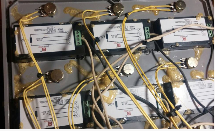
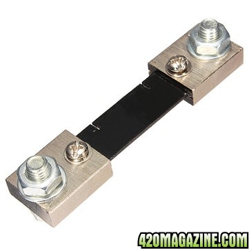
Did fan ever upload a video on how to wire his control box? I'm not an electrician and I'm trying to figure out how to connect the DC digital multifunction monitor from amazon to the driver and cobs. I got a shunt and have no clue wtf that is. I'm try to watch tube vids. Until then, I'll work on the cut outs for the monitor.

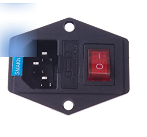
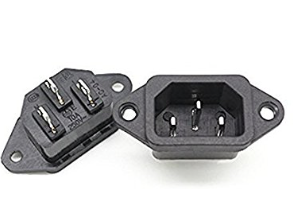
I also got one of these:

power_1.png


which I have no clue how to wire...

Could I use these to simplify the process???
power_2.png
 
If you want to switch power on and off of your drivers that will work, I see it's fused also. Might to use smaller fuse or wire multiple drivers off of it. You'll need the male plug to connect to ac power source. You should be able tell what each pin is from the male plug. Or maybe it has small diagram on it somewhere.

Are you needing diagram on the ac power meters? I can draw you one when I get off work.


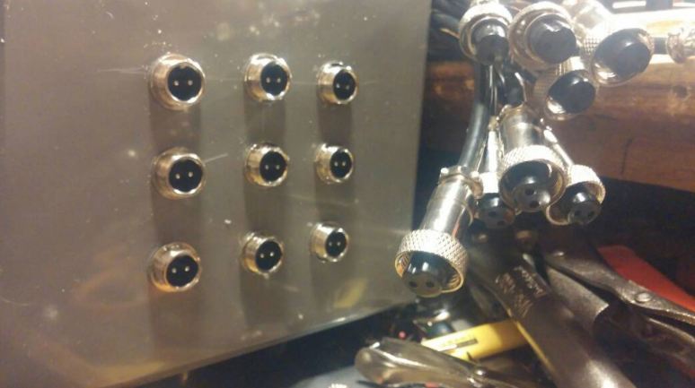
I already attached the 3 prong plug to the ac side of the driver. But I haven't soldered the pot on because I'm trying to use a control box like fans did. He connected the dim wires from the driver to gx 12mm 2 pin aviation connectors that hook up to the control box below.

AVIATION_CONNECTOR.png


I can get those but have no clue how to wire them. I'm assuming it's like a dc barrel connector. If you know how I'd love a drawing or instructions.... but my main concern is the power monitors.

POWER_MONITOR.png


The yellow cables are the dim wires connected to the male aviation connector, but my power monitor has 4 connections one side.

power_monitor_instructions.JPG


plus a shunt

shunt.jpg


I don't know what wires to hook up to the monitor or to the shunt. I don't know where I can place the shunt in the project box I got (abs 12x12x6). Fan only has 1 wire connected to it so I thought I could copy that. I tried making sense of his drawing on post #76 pg 6 but I don't know jack about power,circuits, electricity.

Do I need those power on switches? Is there a work around? If you can post a pic or send me link so I can learn how to wire this part too that'll be great.
 
Back
Top Bottom