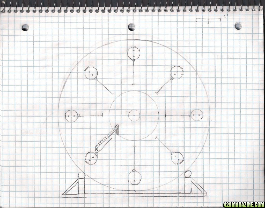
This first view is as if you cut the wheel in half down the center so you're looking at the interior of the wheel. Most of these pictures are self explanatory but may make more sense when the wheel is done being built. Use your best judgment on these and if you have any questions than feel free to ask.
The scale in this first drawing is one square equals 3 inches, so four equals a foot.

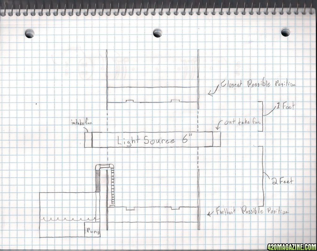
This next view explains how the water will be delivered to the plant pipes on the interior of the wheel. It's likely that the base will house the basin for the nutrient water and thus when the water runs out of the pipes it will drip onto the top of the basin pooling towards the center where I'll place a drain for the water to get back in to the basin. Scale on this one is the same, 1 square equals 3 inches.

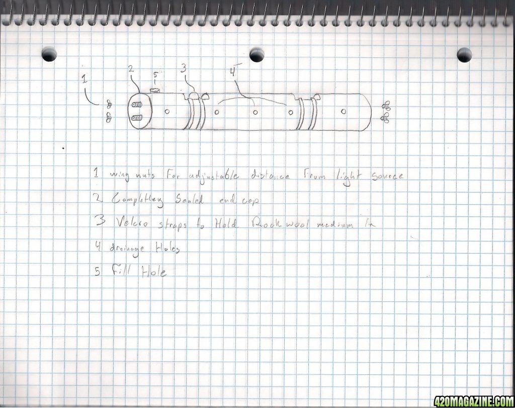
Up next is the pipe that runs from one side of the wheel to the other. I plan on using 6 inch pvc it seems to match the 4 inch cubes of rockwool perfectly, which you'll see in the last picture of this post. Features of the pipe, in case you cant read the words in the picture, are as follows,
1. Wingnuts which are used to adjust the distance from the light source. The scale in this first drawing is one square equals 3 inches, so four equals a foot.

This next view explains how the water will be delivered to the plant pipes on the interior of the wheel. It's likely that the base will house the basin for the nutrient water and thus when the water runs out of the pipes it will drip onto the top of the basin pooling towards the center where I'll place a drain for the water to get back in to the basin. Scale on this one is the same, 1 square equals 3 inches.

Up next is the pipe that runs from one side of the wheel to the other. I plan on using 6 inch pvc it seems to match the 4 inch cubes of rockwool perfectly, which you'll see in the last picture of this post. Features of the pipe, in case you cant read the words in the picture, are as follows,
2. Endcap will be sealed so it will hold the water in. probably be made out of the scrap ply I'll have left over from the wheel.
3. Velcro straps to hold the plant medium in when inverted. im not 100 percent set on this idea so let me know if you think of something better but it will have to have something.
4. Drain holes (These were drawn in the wrong place. Please forgive me!) they will be placed according to the first design plan at the beginning of this post. the will need to point straight down by a certain point to allow as much water to drain as possible. I think it will be something like 225 degrees where the plant is at 0 degrees.
5. Fill hole. I know this looks iffy on the plan but ill figure something out. the pump should be able to "squirt" the nutrient water in sufficiently.

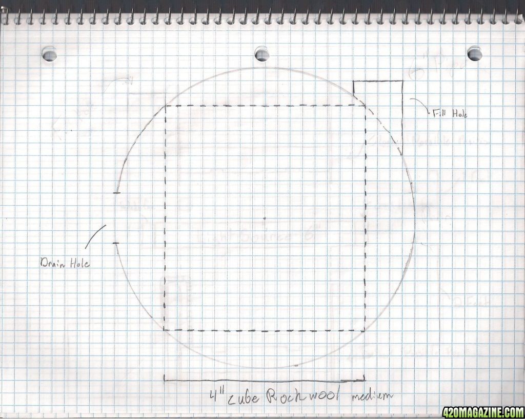
This last one is just a cut away from one of the 6 inch pvc pipes. I wanted to see how well a four inch rockwool cube would fit and it looks like they were made for each other.
scale is 1:1
scale is 1:1

In the next post I'll start construction on the stand. Stay Tuned!!!


